
We're not entirely convinced we're going to make that good a job of the fretboard, so it'll likely sound nasty and out-of-tune all the time. So to make it a playable instrument, we're going to use it like a game controller - getting feedback to indicate which string is being pressed against which fret, to determine which note(s) are being played.
Analogue-to-MIDI stuff is available. But it's mostly very expensive. And, if truth be told, not very good. Jason has an awesome MIDI bass that looks and plays just like a regular bass. But it uses frequency recognition to determine which note is being played (not which string is fretting which note) and that means
a) sometimes it's not very accurate and
b) there's a noticeable delay between plucking the string and hearing the note.
c) it requires dedicated one-signal-per-string pickups
We're going with the crazy idea of building a fingerboard from scratch, placed over a circuit board which contains
a) an array of 72 RGB LEDs (6 strings x 12 frets = 72 lights)
b) a resistor ladder, with a single resistor connecting each fret to the next one
Frets are placed into cutouts in the fingerboard, using "tangs" to hold them in place. Our idea is to solder a connector onto the underside of each tang to connect it to the next resistor in the resistor ladder.

So underneath the fingerboard, we'll have a single resistor ladder covering the first twelve frets of the guitar neck (after the twelfth fret, all patterns repeat).

Why only one resistor ladder when there are six strings? Well, here's how it's going to work:
At the end of the resistor ladder, we have a connection to an analogue input, We're going to use the string to short part of the ladder to ground, effectively changing the ratio between the resistors "above" and "below" where we take our analogue reading from.
We're going to connect our guitar strings to ground, isolating each string from each other by using shrink-wrap where the string touches any metal parts on the bridge or where they pass through the guitar body.

Here we've shown each possible location where you can fret a string as a switch on the circuit diagram. Imagine a guitar with just one string. When no notes are fretted, the resistor ladder acts like a voltage divider with a relatively short resistance between the input pin and the power supply, and a much larger resistance between the input pin and ground (the result being an analogue input which is relatively close to the supply voltage).
Now let's fret a note about half-way along the fingerboard. The string presses against the wire fret, "shortening" the lower part of the resistor ladder, meaning the ratio of resistance between the power supply, the input pin and ground is altered. The closer to the input pin the player frets a note, the closer to ground the analogue input signal becomes.
All this sounds great for a single string. But a guitar has six of them. But each wire fret is going to be conductive no matter which string is pressing against it. If we were to fret, say, the second and fourth frets on the guitar, and query the analogue input pin, only the fret closest to the input pin would actually be making a difference. It's a bit like closing the switches above R1 and R3 in the diagram above - the switch at R3 shortens the length of the resistor ladder - the fact the R1 is also closed makes no difference whatsoever.
What we need to be able to do is to poll the fret position of each string, individually, and to "disconnect" the strings we're not interested in while polling each one.
Sounds tricky? Not really. Thanks to "tri-stating" on our PIC microcontroller inputs, we can do exactly that. We simply make all pins connected to the strings tri-state (set to high-impedance inputs) then make just one string/pin a digital output and pull it to ground.
We then read the analogue input and convert the reading into a fret position. Because we know which string we "activated", we know which fret only that string is in contact with (if any). If another string is being fretted closer to the input pin, it doesn't matter - because that string is "disconnected" from the circuit (as it's connected to a high-impedance input pin).
To prove the concept, we built a simple test-rig
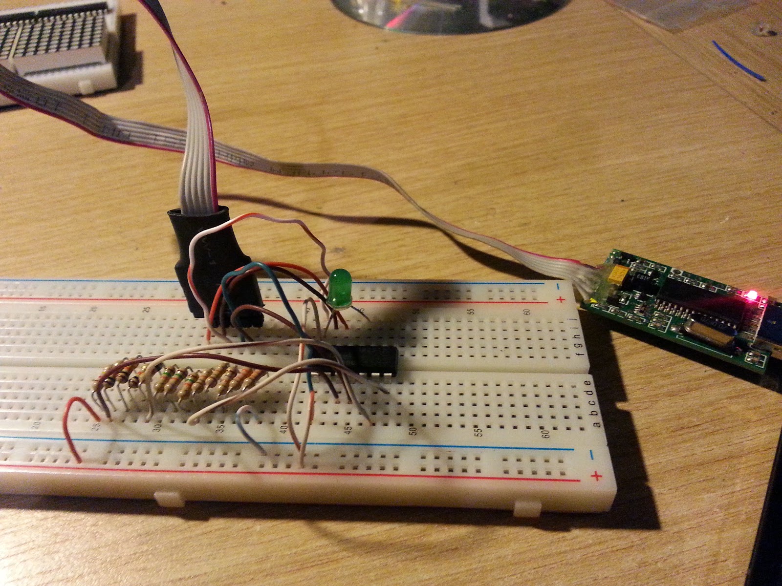
There's our twelve-stage resistor ladder, connected to a PICmicrocontroller (a 16F1825 I think). The first thing to do is to test this, by shorting each resistor to ground, and reading the analogue values recorded by the PIC.
With all equal 10K resistors
| Fret 10: | 384 |
| Fret 9: | 6336 |
| Fret 8: | 11520 |
| Fret 7: | 15936 |
| Fret 6: | 19648 |
| Fret 5: | 23232 |
| Fret 4: | 26240 |
| Fret 3: | 28608 |
| Fret 2: | 31040 |
| Fret 1: | 33472 |
| Fret 0: | 35072 |
| open: | 35392 |
We hit a snag here, because our analogue read routines report varying values, within quite a wide range (this is the nature of analogue reads, normally you take multiple readings and average out the results to get a closest-match). Between frets 4-10 there isn't really much of a problem. But further down, the difference between the values sometimes gets very close to the natural margin for error in our analogue read functions.
It's no good taking a reading from fret zero of 35k +/- 1000 when the reading for fret one might also be 33k +/1000. There's too much chance of an overlap between values and errors, so we looked to reduce this by changing our resistor ladder slightly.
Instead of using all the same resistor values, we made the resistor values larger, closer to the zero fret. So frets 0 and 1 had 23k resistors connecting them to the next rung in the ladder. Frets 2-4 were connected using 18k resistors, frets 5-7 were connected using 15k resistors and all the other frets were connected using 10k resistors.
The results this time were much more encouraging
| Fret 12: | 384 |
| Fret 11: | 6272 |
| Fret 10: | 11328 |
| Fret 9: | 15744 |
| Fret 8: | 19520 |
| Fret 7: | 24256 |
| Fret 6: | 28480 |
| Fret 5: | 31808 |
| Fret 4: | 35200 |
| Fret 3: | 38656 |
| Fret 2: | 40384 |
| Fret 1: | 42624 |
| Fret 0: | 46528 |
| open: | 47040 |
While it would be nice to have wider gaps between the values at the lower valued frets, they're now a reasonable distance apart. With a working resistor ladder, the next thing to do was prove that the whole thing worked with two or more notes fretted (we simulated this by leaving two wires connected at two different points on the resistor ladder, and "activating" only one wire at a time).
Define CONFIG1 = 0x0804
Define CONFIG2 = 0x1dff
Define CLOCK_FREQUENCY = 32
declarations:
Symbol led_out = PORTC.0
Symbol analogue_in = PORTA.4
Symbol tx = PORTA.0
Dim b As Byte
Dim r As Byte
Dim iw As Word
init:
OSCCON = 11110000b '32Mhz internal
APFCON0 = 01000000b 'alternative tx/rx for pickit2
ANSELA = 00010000b 'make PORTA.4 an analogue input (all others digital)
ANSELC = 0x00 'PORTC is all digital
ConfigPin led_out = Output
ConfigPin analogue_in = Input
ConfigPin PORTC = Input
Define ADC_CLOCK = 3
Define ADC_SAMPLEUS = 50
b = 0
r = 0
loop:
High led_out
WaitMs 500
'make all of PORTC inputs (tristated/disconnected)
ConfigPin PORTC = Input
Select Case r
Case 0
'do nothing: let's see what value we get
'(57k on average, but sometimes as low as 53k)
Case 1
'make c4 an output and pull it low. This should
'short the fifth resistor to ground and our reading
'should be somewhere in the 49k-45k range
ConfigPin PORTC.4 = Output
Low PORTC.4
Case 2
'make c4 an output and pull it low. This should
'short the sixth resistor to ground and our reading
'should be somewhere in the 53k-50k range
ConfigPin PORTC.3 = Output
Low PORTC.3
EndSelect
'wait a sec
WaitMs 2
'read the analogue input
'RA4 is AD channel 3
Adcin 3, b
iw.HB = ADRESH
iw.LB = ADRESL
Serout tx, 9600, "input "
Serout tx, 9600, #r
Serout tx, 9600, ": "
Serout tx, 9600, #iw, CrLf
Low led_out
WaitMs 500
r = r + 1
If r > 2 Then
Serout tx, 9600, CrLf
r = 0
Endif
Goto loop
End
We have two different i/o lines connected (the white coloured wires at the bottom of the photo). In firmware we "activate" each digital i/o pin, and read the analogue input, while leaving the other wire(s) connected.
| Results with two wires connected: | |
| input 0 | 48576 |
| input 1 | 15808 |
| input 2 | 31872 |
| input 0 | 50048 |
| input 1 | 15040 |
| input 2 | 31680 |
| input 0 | 48576 |
| input 1 | 15808 |
| input 2 | 31872 |
| input 0 | 48704 |
| input 1 | 15808 |
| input 2 | 31936 |
Looking up these values on our previous table of results, we can see that a value of around 15k corresponds to a note at the 9th fret being held, while a value of around 31k is typical of a note at the 5th fret being fretted.
Looking at the photo of the breadboard, we can see that these are the positions of the wires during testing, thus demonstrating that it doesn't matter if more than one string is connected to more than one fret - we can poll each string independently of the others to work out which note is being held on each string.
That's enough for tonight. It's always pleasing to end the weekend being able to demonstrate that an idea or theory does, in fact, work!
No comments:
Post a Comment