Monday 23 February 2015

Sending MIDI messages from our MIDI keyboard

Originally we hadn't planned on creating a complete MIDI keyboard. The idea was to simply modify an existing (working) keyboard and add some lights to it. The Oregon keyboard we eventually went with just looked so cool, would couldn't pass it up - even if it meant buying it "sold as seen".

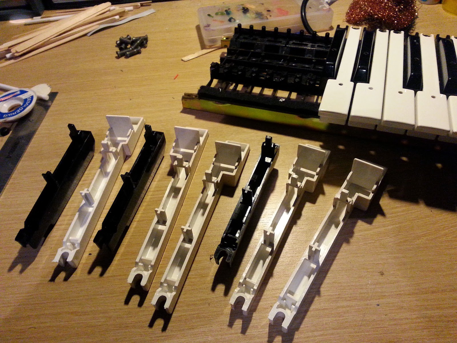
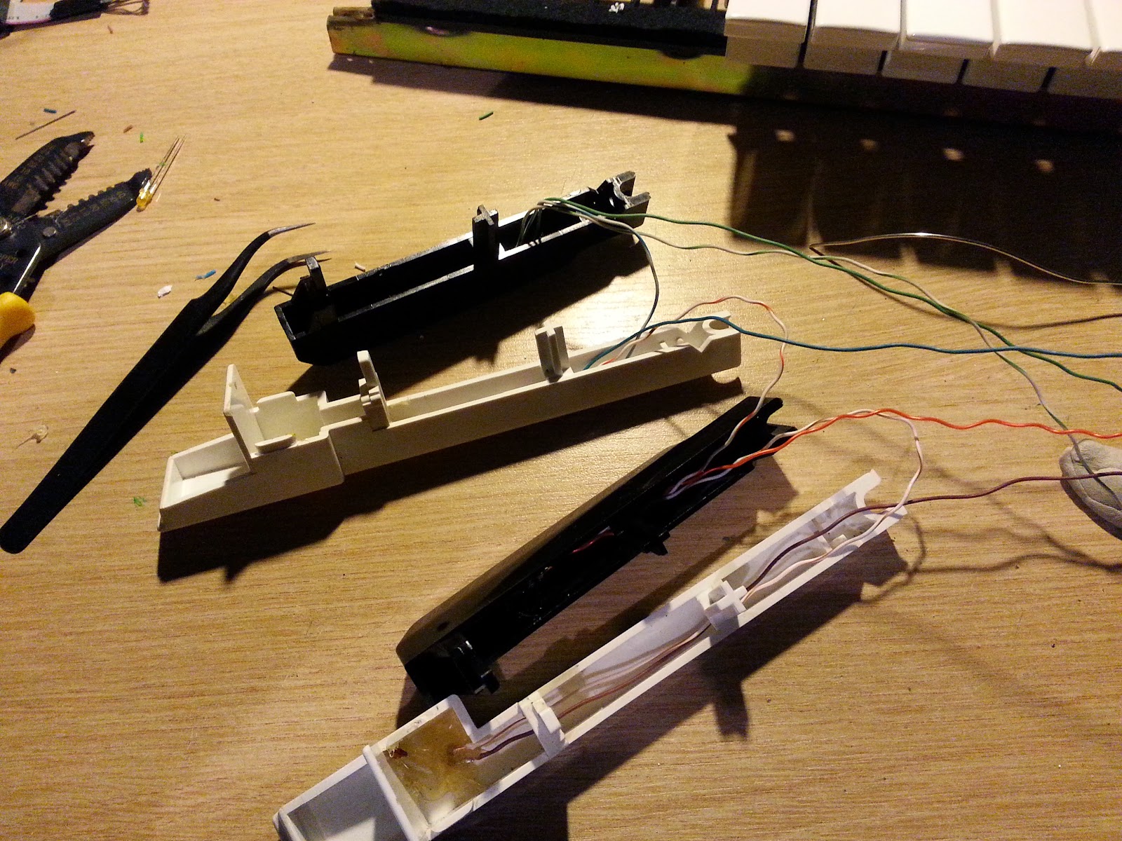
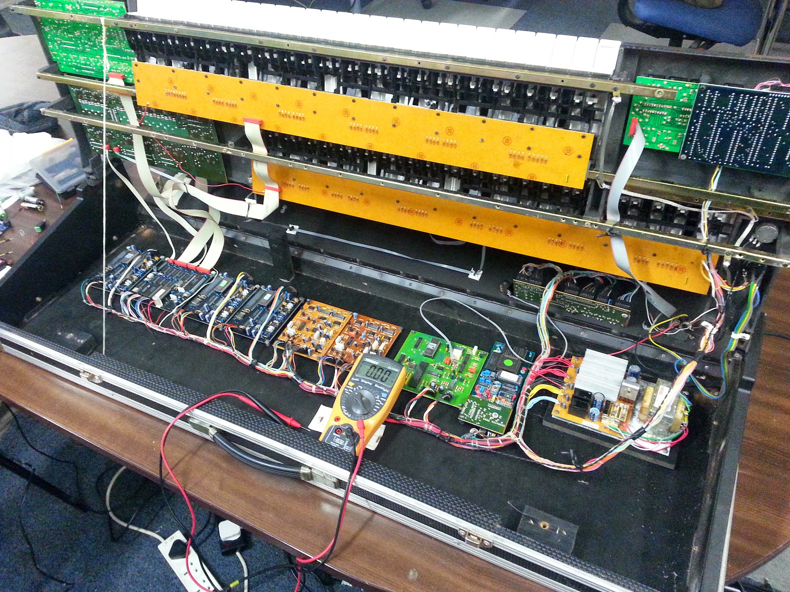
And although it was seen with all the lights working, ultimately it turned out that it was "sold as broken". So we've had to gut the thing completely and build our own controller for it, as well as add in our light-up keys.

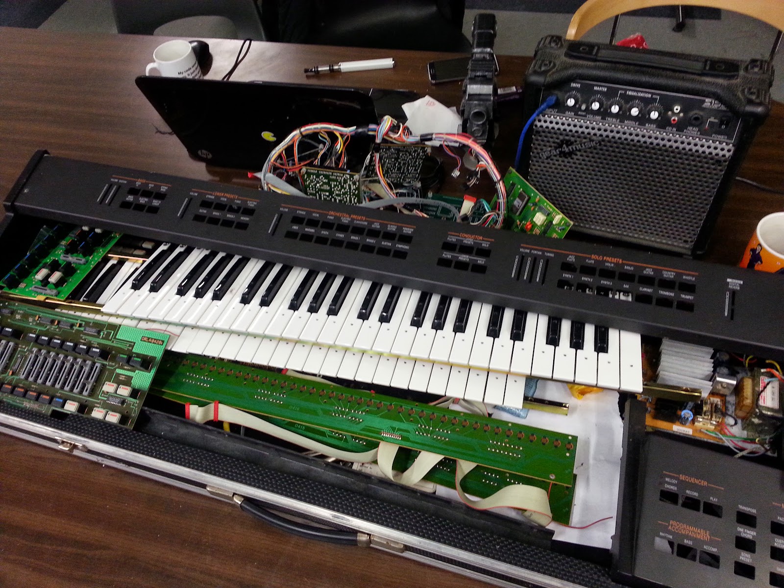
This does have a few benefits (despite meaning loads more work) - firstly, we'll be able to use any MIDI soundbank as we like (the keyboard was first built in the mid-80s and some of the synthesized sounds were... erm, a bit sketchy to say the least!). It also means we've about a million un-used buttons and sliders all over the original casing, which we can re-use for any purpose we like.

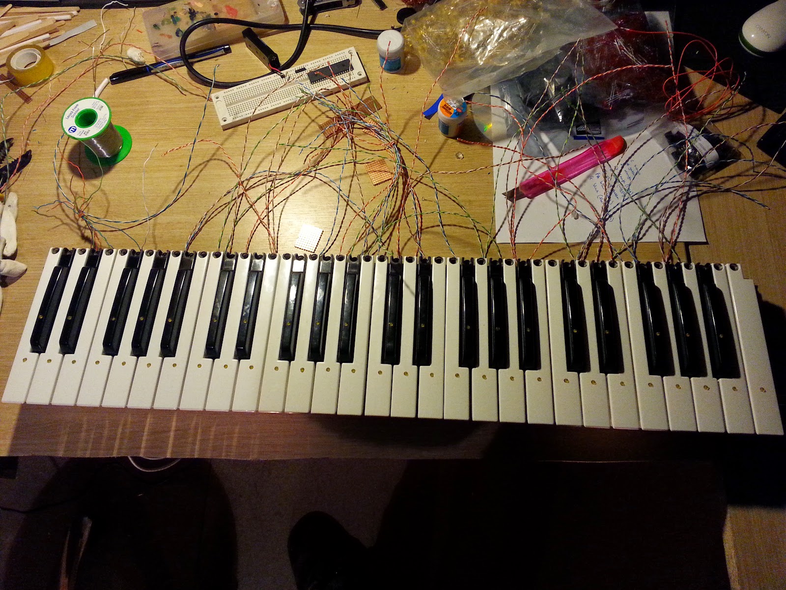
Luckily, the original device used a relatively simple 8-bit multiplexing method of reading the entire keypad - or at least, if it didn't the hardware suggests that it did something very similar.


We can read each bank of eight keys by sending their common line low and detecting which of our input pins has gone low (indicating that a key has been pressed). Then we send the common line of the next back of keys low, and detect which of those keys have been pressed by monitoring the same set of 8 input pins. The reason we think this is how the keyboard originally worked is because every single pad on the breakout circuit board has been connected with a diode, which isolates each bank of eight keys and only allows the current to flow "from" the keypad connector "towards" the common rail - the ideal set-up if you're using pull-up resistors on your input pins, and shorting the keys to ground when they are pressed.

So now we can detect keypresses, we need to monitor (and remember) the state of each key as it is both pressed and released.

Voice MessageStatus ByteData byte1Date byte2
Note off8xKey numberNote Off velocity
Note on9xKey numberNote On velocity
Polyphonic Key PressureAxKey numberPressure amount
Control changeBxControl numberControl value
Program changeCxProgram number-
Channel pressureDxPressure value-
Pitch bendExMSBLSB


We're going to be focussing on note on and off signals (our hardware isn't really set up for velocity, so we'll just set this to "full whack" - or maybe make it an editable option). We may use control and program change messages for some of the re-purposed buttons, but for now let's concentrate on getting the keys working: there's no point having a MIDI keyboard that doesn't detect and respond to keypresses!

Our 49 keys mean storing the current state of each key across seven bytes. We're going to imagine these bytes not in groups of eight bits, but as one, big, massive 56 bit value. Simply put, each time a key is pressed, we set the corresponding bit in this big long number to a one, and when it is released, we un-set the corresponding bit to zero.

Each time we read the input port, we compare the value on the input pins to the corresponding byte in this big long number (since the keys are read in groups of eight also). If they are the same, then nothing has changed.

If they are different, we look to see whether a bit value has gone from zero to one (a key has been pressed) or a bit has gone from one to zero (a key has been released). We can then generate and send the appropriate MIDI signal.


When we start, all our values are zero (all the keys are released). Let's say we hit a C-major chord. The first byte is now 10001001 and the second byte is 00001000 (if we do this higher up the keyboard, it may be the third and fourth bytes, or the same pattern may be split over bytes two and three, but you get the idea).

To detect keypresses we do this: Take the previous pattern and XOR the current key pattern over it.
This gives us all the keys that have recently changed - note, this isn't necessarily the keys that have just been pressed, as we'll soon see.
So our original pattern of

00000000 00000000 XOR
10001001 00001000 =
===============
10001001 00001000

While this does correspond to all the keys that we've just pressed, it's important to understand that this is a pattern of keys that have changed. The next time we scan the keypad, we get

10001001 00001000 XOR (previous pattern of keys pressed)
10001001 00001000 = (current pattern of keys pressed)
===============
00000000 00000000 (nothing has changed).

Now let's release the keys and see what happens:
10001001 00001000 XOR (previous pattern of keys pressed)

00000000 00000000 = (current pattern of keys pressed)
===============
10001001 00001000 (the keys that make up the C major chord have changed)

So we're able to detect which keys  have changed - now we need to work out whether the key has been pressed or released. We need to do this is two stages - first work out which keys have been released then work out which keys have been pressed:

Take the pattern of keys that have changed and bit-wise AND with the current (input) pattern.

Any change from nothing to C-major to nothing again isn't going to demonstrate things as nicely as changing from one chord to another, so here goes - we're going from C to Cm7 (hey, maybe this is some quirky jazz number or something?)


We're holding down a C major chord, which we represent (in binary) as 1000100100001000
Now let's move to C minor 7th, which is represented as 1001000100100000

First, get the keys that have changed by bit-wise XOR-ing the two values:

1000100100001000 XOR (before)
1001000100100000 = (after)
===============
0001100000101000

The changed pattern shows not only the keys that have been released, but also the keys that have been pressed. So let's get the keys that have been released first (assuming you lift your fingers off the keys before placing them in new locations).

Take the resultant "changes" pattern and bitwise AND it with the previous pattern

0001100000101000 AND (result)
1000100100001000 = (previous pattern)
==============
0000100000001000

And if we compare this back to the keyboard, we can see that we've identified


And it turns out that these are the two keys that we've lifted off. So far so good. Now let's work out which keys have just been pressed. To do this we bitwise AND the current (input) pattern with the resulting pattern of changes.

0001000000100000 AND (result)
1001000100100000 = (new/current pattern)
===============
0001000000100000

And if we compare this back to the keyboard, we've identified


and it just so happens that these are the two keys we've just pressed/added to the previous chord. The notes that didn't change (the C and the G) don't appear anywhere, because they didn't actually change.

So there we have it - we create a pattern to find out which keys have changed by XOR-ing the current pattern with the previous pattern.

To find out which keys have been released, we AND this result with the previous pattern. To find out which keys have been pressed, we AND this result with the current pattern.

Now we can detect keys being pressed and released, we need to send our MIDI messages to the synthesizer/midi sequencer. We'll add some clever stuff in later, to change which channel we're sending data on, so for now, we'll assume channel one (but it could be any channel from zero to 15).

Most ad-hoc MIDI messages are made up of just a simple three byte packet. The upper half of the first byte is 8 for a note off message (1000----). The lower half of the byte is channel number (we're using 1 for now ----0001). So our first byte, for any key release will start with 0x81 (or 10000001 in binary).

The second byte is the note value, in the range 21-108, where 0 is low A0 (27.5hz) and 108 is C8 (4186hz). Concert pitch A (the note most instruments use as a reference for tuning, at 440hz) is MIDI note number 69 (decimal, 0x45 in hex).

Note a note on MIDI values - all values (except for the first byte) must remain in the range 0-127. This allows MIDI devices to detect the beginning of a midi message - it should be the only byte in the entire packet that has the MSB set to one; all values contained within the message should always have a MSB un-set to zero.

The final byte in a MIDI message is the velocity (how hard you hit the note). We're going to just use a global variable for this - so you can set the velocity for every key, else just set it to maximum (0x7F - note that the leading MSB is cleared).

That's as simple as our MIDI messaging needs to be.

For key presses, we do exactly the same, except the first byte will begin 0x91 (the upper half of the first byte set to 0x09 indicates a note on, whereas 0x08 indicates note off).

We've a whole load of buttons still to mount into the enclosure when the time comes, which means we could have control change messages and system messages and all that kind of stuff floating around - but we're going to stick to simple note on and note off messages for now.


Tuesday 17 February 2015

MIDI keyboard - lights test

It all started this evening, with a simple lights test, animating through a full octave on the keyboard.


Wiring individual LEDs to the MAX7219 wasn't quite as straight-forward as wiring an 8x8 LED matrix (though quite why, we're still not sure). But, after a bit of fiddling about and debugging by plugging just one set of wires in at a time, we eventually got some working firmware for our light-up keyboard.


It's all pretty encouraging - dial in a chord or scale and all the available notes correctly light up! There are a few modes of operation. At the minute we're using a rotary dial to select everything, but in time, we'll use the second keypad to select the current key/scale, and plenty of different buttons to quickly and easily change between minor, major, full scale, chords etc.

In "chord" mode, it's pretty obvious what's happening: the chord shape is repeated in two places on the keyboard (originally we were going to just display it once, but then thought we've no idea whether the player would want to use their left hand or their right hand to play the chord - so put a chord shape under each!).

In "show full chord" mode, all of the notes that make up the select chord appear across the entire keyboard. This is  a bit like showing a scale, but not quite. For example, a C major chord (based on the triad of C-E-G) is very different to the C major scale (consisting of the seven notes C-D-E-F-G-A-B). So what's the point?

Chords/triads have lots of different inversions.
A C major chord doesn't have to start with the lowest note on C.
You can play a C major chord as G-C-E. This is known as the "second inversion" (the first inversion is played E-G-C). So by displaying all the notes of the chord and repeating them multiple times over, you can simply play any consecutive three notes and you'll get a C major - even if you're not starting on the root note C.

Full scale mode is pretty self-explanatory: select a scale and the entire scale is displayed across the entire keyboard. This should make it easy for players to jam along, much like a guitarist might do, when playing a solo. If you know the song is, for example, a shuffle/blues in A, there's no reason why you can't dial in "A pentatonic" and you can pick pretty well any notes out of the scale and produce something vaguely melodic (that's how a lot of guitar players do it anyway!)


Monday 16 February 2015

MIDI keyboard wired and ready for testing

It's been a frantic, weekend-long project (ok, not including the dismantling and drilling we did on Thursday night) and the wiring is nowhere near as neat and tidy as it was in the original, but the first/top entire keyboard is now wired up and ready for testing

The LEDs in the keys have their cathode (ground) pins wired together in groups of eight. And we meticulously numbered every "power" side wire with little flags, so we'd know which wires to common together for the MAX7219 controller when it comes to driving the LEDs.


The whole thing took maybe a full day in total (Nick and I were out playing petanque/boules for most of Saturday daytime, and we had about eight hours at the soldering station on Sunday).

So now we've over a hundred solid-core(?!) wires stripped, soldered, cut-to-length and taped together (yes Steve, taped together with crappy old sellotape - no heatshrink here for us!) in a kind of wiring loom.


Some of the wires still need cutting to length, but we left them overly long, for testing on a breadboard. When it comes to it, we'll probably just solder the wires as they are and just stuff them all inside the case - after all, there'll be plenty of room inside now we've taken all that old circuitry out!

It's late now, so it'll probably be tomorrow (Monday) evening before we get any firmware running to test it all out. With a bit of luck, we'll have at least one of the two decks working fully before the next boogie-woogie band practice on Tuesday night, and we'll be able to try it out for real.

Saturday 14 February 2015

Code for displaying scales as binary on a PIC 18F4550 microcontroller

Here's the code so far, for selecting a scale/chord and displaying all the associated notes across a keyboard. It's by no means complete - there's no key-scanning to find out which keys are pressed, but you can dial in a chord or scale, and set the key, and see what the binary output would look like.

Define CONFIG1L = 0x00
Define CONFIG1H = 0x0c
Define CONFIG2L = 0x18
Define CONFIG2H = 0x1e
Define CONFIG3L = 0x00
Define CONFIG3H = 0x01
Define CONFIG4L = 0x80
Define CONFIG4H = 0x00
Define CONFIG5L = 0x0f
Define CONFIG5H = 0xc0
Define CONFIG6L = 0x0f
Define CONFIG6H = 0xe0
Define CONFIG7L = 0x0f
Define CONFIG7H = 0x40

Define CLOCK_FREQUENCY = 20
AllDigital

declarations:

     Define LCD_BITS = 4 'allowed values are 4 and 8 - the number of data interface lines
     Define LCD_DREG = PORTA
     Define LCD_DBIT = 0 '0 or 4 for 4-bit interface, ignored for 8-bit interface
     Define LCD_RSREG = PORTA
     Define LCD_RSBIT = 4
     Define LCD_EREG = PORTA
     Define LCD_EBIT = 5
     Define LCD_RWREG = PORTA 'set to 0 if not used, 0 is default
     Define LCD_RWBIT = 0 'set to 0 if not used, 0 is default

     Define LCD_COMMANDUS = 2000 'delay after LCDCMDOUT, default value is 5000
     Define LCD_DATAUS = 50 'delay after LCDOUT, default value is 100
     Define LCD_INITMS = 2 'delay used by LCDINIT, default value is 100
     'the last three Define directives set the values suitable for simulation; they should be omitted for a real device

     Dim state As Byte
     Dim mode As Byte
     Dim output_buffer(8) As Byte 'we can display up to 64 leds
     Dim scale_notes(8) As Byte 'we can store up to 64 notes
     Dim scale_pattern(3) As Byte 'each 24 note (two octave) pattern repeats over 3 bytes
     Dim req_pattern_type As Byte

     Symbol rotary_pulse = PORTE.1
     Symbol rotary_direction = PORTE.0
     Symbol rotary_button = PORTE.2

     Dim last_pulse As Bit
     Dim curr_direction As Byte
     Dim curr_button As Bit

     Dim current_key As Byte
     Dim notes_pattern As Long '(4 byte value, 3 bytes + 1st byte repeated)
     Dim pattern_mask As Long
     Dim chord_scale_type As Byte

     Dim i As Byte
     Dim j As Byte
     Dim k As Byte
     Dim h As Word

initialise:

     state = 0
     req_pattern_type = 0
     notes_pattern = 0
     current_key = 0 '(0=C, 1=C#, 2=D, 3=Eb, 4=E, 5=F, 6=F#, 7=G, 8=G#, 9=A, 10=Bb, 11=B)
     last_pulse = rotary_pulse
     Lcdinit

     INTCON2.RBPU = 0 'enable pullups on PORTB
     PORTE.7 = 1 'enable pullups on PORTD

     ConfigPin PORTB = Input
     ConfigPin PORTD = Input
     ConfigPin PORTE = Input 'portE has external pull-ups on E0-E2

loop:

     Select Case state


           Case 0
           Lcdcmdout LcdClear
           Lcdout "Keyboard"
           Lcdcmdout LcdLine2Home
           Lcdout "Controller v1.0"
           WaitMs 1500
           mode = 0
           state = 1

           Case 1
           Lcdcmdout LcdClear
           Lcdout "Select mode:"
           Lcdcmdout LcdLine2Home
           Select Case mode
                 Case 0
                 Lcdout "Single chord "

                 Case 1
                 Lcdout "All chord notes "

                 Case 2
                 Lcdout "Full scale "

                 Case 3
                 Lcdout "Walking bassline"

                 Case 4
                 Lcdout "MIDI input mode "
           EndSelect
           state = 2


           Case 2
           'wait for the rotary dial
           curr_direction = 0
           curr_button = 0
           Gosub read_rotary

           If curr_direction = 1 Then
                 If mode > 0 Then mode = mode - 1 Else mode = 4
                 state = 1
           Endif

           If curr_direction = 2 Then
                 mode = mode + 1
                 If mode > 4 Then mode = 0
                 state = 1
           Endif

           If curr_button = 1 Then
                 state = 3
           Endif


           Case 3
           Lcdcmdout LcdClear
           If mode = 0 Then
                 Lcdout "Chord type:"
                 chord_scale_type = 0
                 state = 4
           Endif
           If mode = 1 Then
                 Lcdout "Chord type:"
                 chord_scale_type = 0
                 state = 4
           Endif
           If mode = 2 Then
                 Lcdout "Scale type:"
                 chord_scale_type = 100
                 state = 10
           Endif
           If mode = 3 Then
                 Lcdout "Walking bassline"
                 chord_scale_type = 120
                 state = 20
           Endif
         
           If mode = 4 Then
                 Lcdout "MIDI mode"
                 state = 200
           Endif


           Case 4
           Lcdcmdout LcdLine2Home
           Select Case chord_scale_type
                 Case 0
                 Lcdout "Major chord "

                 Case 1
                 Lcdout "Minor chord "

                 Case 2
                 Lcdout "Dominant 7th "

                 Case 3
                 Lcdout "Major 7th chord "

                 Case 4
                 Lcdout "Minor 7th chord "
           EndSelect
           state = 5


           Case 5
           'wait for the rotary dial
           curr_direction = 0
           curr_button = 0
           Gosub read_rotary

           If curr_direction = 1 Then
                 If chord_scale_type > 0 Then chord_scale_type = chord_scale_type - 1 Else chord_scale_type = 4
                 state = 4
           Endif

           If curr_direction = 2 Then
                 chord_scale_type = chord_scale_type + 1
                 If chord_scale_type > 4 Then chord_scale_type = 0
                 state = 4
           Endif

           If curr_button = 1 Then
                 Lcdcmdout LcdClear
                 Lcdout "Select chord:"
                 state = 6
           Endif
           Gosub read_from_keys


           Case 6
           Lcdcmdout LcdLine2Home
           Gosub display_key
           If chord_scale_type = 0 Then Lcdout "major "
           If chord_scale_type = 1 Then Lcdout "minor "
           If chord_scale_type = 1 Then Lcdout "dominant 7th "
           If chord_scale_type = 3 Then Lcdout "major 7th "
           If chord_scale_type = 4 Then Lcdout "minor 7th "
           Gosub display_output
           state = 7


           Case 7
           'wait for the rotary dial
           curr_direction = 0
           curr_button = 0
           Gosub read_rotary

           If curr_direction = 1 Then
                 If current_key > 0 Then current_key = current_key - 1 Else current_key = 11
                 state = 6
           Endif

           If curr_direction = 2 Then
                 current_key = current_key + 1
                 If current_key > 11 Then current_key = 0
                 state = 6
           Endif

           If curr_button = 1 Then
                 state = 1
           Endif
           Gosub read_from_keys


           Case 10
           Lcdcmdout LcdLine2Home
           Select Case chord_scale_type
                 Case 100
                 Lcdout "Major scale "

                 Case 101
                 Lcdout "Minor scale "

                 Case 102
                 Lcdout "Penatonic scale "

                 Case 103
                 Lcdout "Blues scale "
           EndSelect
           state = 11

           Case 11
           'wait for the rotary dial
           curr_direction = 0
           curr_button = 0
           Gosub read_rotary

           If curr_direction = 1 Then
                 If chord_scale_type > 100 Then chord_scale_type = chord_scale_type - 1 Else chord_scale_type = 103
                 state = 10
           Endif

           If curr_direction = 2 Then
                 chord_scale_type = chord_scale_type + 1
                 If chord_scale_type > 103 Then chord_scale_type = 100
                 state = 10
           Endif

           If curr_button = 1 Then
                 Lcdcmdout LcdClear
                 Lcdout "Select scale:"
                 state = 12
           Endif


           Case 12
           Lcdcmdout LcdLine2Home
           Gosub display_key
           If chord_scale_type = 100 Then Lcdout "major scale "
           If chord_scale_type = 101 Then Lcdout "minor scale "
           If chord_scale_type = 102 Then Lcdout "pentatonic "
           If chord_scale_type = 103 Then Lcdout "blues scale "
           Gosub display_output
           state = 13


           Case 13
           'wait for the rotary dial
           curr_direction = 0
           curr_button = 0
           Gosub read_rotary

           If curr_direction = 1 Then
                 If current_key > 0 Then current_key = current_key - 1 Else current_key = 11
                 state = 12
           Endif

           If curr_direction = 2 Then
                 current_key = current_key + 1
                 If current_key > 11 Then current_key = 0
                 state = 12
           Endif

           If curr_button = 1 Then
                 state = 1
           Endif


           Case 20
           Lcdcmdout LcdLine2Home
           Lcdout "Walking bass: "
           Gosub display_key
           Gosub display_output
           state = 21


           Case 21
           'wait for the rotary dial
           curr_direction = 0
           curr_button = 0
           Gosub read_rotary

           If curr_direction = 1 Then
                 If current_key > 0 Then current_key = current_key - 1 Else current_key = 11
                 state = 20
           Endif

           If curr_direction = 2 Then
                 current_key = current_key + 1
                 If current_key > 11 Then current_key = 0
                 state = 20
           Endif

           If curr_button = 1 Then
                 state = 1
           Endif
           Gosub read_from_keys


     EndSelect

     'now if the output buffers have changed since last time, update the shift register(s)

     Goto loop
     End

set_scale_pattern:

     Select Case req_pattern_type
           Case 0 'major chord (10001001 00001000 10010000)
           scale_pattern(0) = 10001001b
           scale_pattern(1) = 00001000b
           scale_pattern(2) = 10010000b

           Case 1 'minor chord (10010001 00001001 00010000)
           scale_pattern(0) = 10010001b
           scale_pattern(1) = 00001001b
           scale_pattern(2) = 00010000b

           Case 2 'dominant 7th chord (10001001 00101000 10010010)
           scale_pattern(0) = 10001001b
           scale_pattern(1) = 00101000b
           scale_pattern(2) = 10010010b

           Case 3 'major 7th chord (10001001 00011000 10010001)
           scale_pattern(0) = 10001001b
           scale_pattern(1) = 00011000b
           scale_pattern(2) = 10010001b

           Case 4 'minor 7th chord (10010001 00011001 00010001)
           scale_pattern(0) = 10010001b
           scale_pattern(1) = 00011001b
           scale_pattern(2) = 00010001b

           Case 5 'major scale (10101101 01011010 11010101)
           scale_pattern(0) = 10101101b
           scale_pattern(1) = 01011010b
           scale_pattern(2) = 11010101b

           Case 6 'minor scale (10110101 10101011 01011010)
           scale_pattern(0) = 10110101b
           scale_pattern(1) = 10101011b
           scale_pattern(2) = 01011010b

           Case 7 'minor pentatonic scale (10010101 00101001 01010010)
           scale_pattern(0) = 10010101b
           scale_pattern(1) = 00101001b
           scale_pattern(2) = 01010010b

           Case 8 'minor blues scale (10010111 00101001 01110010)
           scale_pattern(0) = 10010111b
           scale_pattern(1) = 00101001b
           scale_pattern(2) = 01110010b

           Case 10 'walking bass line (10001001 01101000 10010110)
           scale_pattern(0) = 10001001b
           scale_pattern(1) = 01101000b
           scale_pattern(2) = 10010110b

     EndSelect

Return

read_rotary:
     If rotary_pulse = 0 And last_pulse <> 0 Then
           'on any edge (rising or falling) check to see
           'which way the rotary is being turned
           If rotary_direction = 0 Then
                 curr_direction = 2
                 Else
                 curr_direction = 1
           Endif
           WaitMs 25
     Endif
     last_pulse = rotary_pulse

     If rotary_button = 0 Then
           'debounce:
           WaitMs 10
           If rotary_button = 0 Then
                 While rotary_button = 0
                       'wait for release
                 Wend
                 curr_button = 1
           Endif
     Endif
Return

display_key:
     If current_key = 0 Then Lcdout "C "
     If current_key = 1 Then Lcdout "C# "
     If current_key = 2 Then Lcdout "D "
     If current_key = 3 Then Lcdout "Eb "
     If current_key = 4 Then Lcdout "E "
     If current_key = 5 Then Lcdout "F "
     If current_key = 6 Then Lcdout "F# "
     If current_key = 7 Then Lcdout "G "
     If current_key = 8 Then Lcdout "G# "
     If current_key = 9 Then Lcdout "A "
     If current_key = 10 Then Lcdout "Bb "
     If current_key = 11 Then Lcdout "B "

Return

display_output:

     'this is where we actually light up the LEDs
     If chord_scale_type >= 0 And chord_scale_type <= 4 Then req_pattern_type = chord_scale_type
     If chord_scale_type >= 100 And chord_scale_type <= 103 Then req_pattern_type = chord_scale_type - 95
     If chord_scale_type = 120 Then req_pattern_type = 10
         
     Gosub set_scale_pattern

     'load the pattern into a 4-byte Long, repeating the first byte at the fourth (reading from right to left)
     notes_pattern.4B = scale_pattern(0)
     notes_pattern.3B = scale_pattern(1)
     notes_pattern.HB = scale_pattern(2)
     notes_pattern.LB = scale_pattern(0)

     'now shift the pattern into the appropriate key
     If current_key <= 8 Then
           'bit-shift the entire pattern to the right
           If current_key > 0 Then notes_pattern = ShiftRight(notes_pattern, current_key)
           Else
           'to raise by 9 or more steps, we need to "flatten" by shifting left
           'so a raise of 9 steps is the same as a lowering by 3, raising 10 is the same as lowering by 2,
           'raising by 11 is the same a lowering by one (raising by 12 is just an octave higher)
           k = 12 - current_key
           notes_pattern = ShiftLeft(notes_pattern, k)

           'but now we could have blanks in the lowest (fourth) byte, but since this is always
           'just a copy of the highest (first) byte, simply copy it over
           k = notes_pattern.4B
           notes_pattern.LB = k
     Endif

     'if we've shifted left, this following function won't do anything
     'but if we've shifted right, we could potentially have some leading blanks/zeros,
     'so we need to OR the fourth byte with the first, to fill in any missing notes
     k = notes_pattern.4B
     j = notes_pattern.LB
     k = k Or j
     notes_pattern.4B = k

     'if we only want to display a single chord, we only want to display 11 intervals,
     'starting at the root note of the key we're in (maybe do the same for walking bass line?)
     If mode = 0 Or mode = 3 Then
           pattern_mask = 0
           pattern_mask.4B = 11111111b
           pattern_mask.3B = 11110000b

           If current_key > 0 Then pattern_mask = ShiftRight(pattern_mask, current_key)
           notes_pattern = notes_pattern And pattern_mask
     Endif


     'now put the pattern out onto the LEDs

     '(for now we'll write it out to the LCD)
     Lcdcmdout LcdLine1Home
     k = notes_pattern.4B
     Gosub show_k_as_hex
     Lcdout " "
     k = notes_pattern.3B
     Gosub show_k_as_hex
     Lcdout " "
     k = notes_pattern.HB
     Gosub show_k_as_hex
     Lcdout " "

Return

read_from_keys:
     'here we do some multiplexing to see which keys (if any) have been pressed/released
     'since the last scan. The keyboard hardware already has pushbutton type pads in groups
     'of eight, so multiplexing seems the obvious way to go.


Return

show_k_as_hex:
     j = k And 11110000b
     j = ShiftRight(j, 4)
     Gosub show_j_as_hex
     j = k And 00001111b
     Gosub show_j_as_hex
Return

show_j_as_hex:
     If j < 10 Then Lcdout #j
     If j = 10 Then Lcdout "A"
     If j = 11 Then Lcdout "B"
     If j = 12 Then Lcdout "C"
     If j = 13 Then Lcdout "D"
     If j = 14 Then Lcdout "E"
     If j = 15 Then Lcdout "F"
Return


While it's very much a work in progress, this should be enough to get you started with the basic chord and scale types (major/minor/pentatonic etc). Other scales and modes can easily be added in future, as they are required.

Once we've got the hardware wired up, we may even add in some way of reading which chord is being played on the lower deck, and have the appropriate notes for the corresponding scale appear on the upper deck. That's a way off yet, but this code is at least a start....

Creating repeating musical scales in binary

Inbetween soldering and gluing, we've been adding a bit to the firmware for our light-up MIDI keyboard. We're looking to make a generic system for adding scales and chords using simple three-byte patterns. While we're already well into the actual hardware build, it's time to add a bit more to our music-theory-to-binary idea.

Let's start with a really nasty scale on the piano. Here's a C minor blues scale. It's like the C minor penatonic but with an added "blue note". This means a mix of lots of black and white notes. Super confusing!


You can see that there are six notes in the scale, and they repeat over and over on each octave of the keyboard. We're currently describing one octave as twelve intervals in binary. This is basically a byte and a half. So we can store two octaves over three bytes. The third repeating octave is simply a repeat of the first and half of the second byte, and so on.

So our twelve-interval representation of the blues scale is

100101110010

And a two octave span for the C minor blues scale is

100101110010100101110010

And splitting this up into bytes, we get

10010111 00101001 01110010

Where our scale is split over the middle byte:

[10010111  0010][1001  01110010]

If we wanted to play this same scale in D, we simply bit-shift the entire pattern two places to the right:

00100101  11001010 01011100 10

and we're now spanning four bytes.
However, it's worth noting that the final byte is simply the first two notes of the scale as it repeats.
If we continued the sequence, we'd get

00100101  11001010 01011100 10100101  11001010 10100101  11001010

So other than the very first byte, our fourth, seventh, tenth (and so on) bytes are all the same. If truth be told, our first byte should be the same too. We pushed everything up two places, to start on the D instead of the C and simply padded the gaps with "blank" notes. But if we played down the scale instead of upwards, some of these blanks would be over notes in the scale. So there's no reason why we can't "merge" the first and fourth bytes together, to complete the scale in both directions.

Simply put, as we push our scale "out of" the third byte and into the fourth, we can then bitwise OR the first and fourth bytes together, to "fill in the blanks".

In musical notation, you can "push" a scale six places up (this is often referred to as making the notes "sharp") or push a scale down up to six places (referred to as "flattening" the notes). Once you push the notes more than six places in any direction, because of the repeating nature of the notes in a scale (or on a keyboard) you'll find it's the same as pushing them from the other direction. So, for example, you can sharpen all the notes 8 places, but this is the same as flattening all the notes 4 places.

To keep things simple, we're just going to "push upwards" from a basic C scale for everything. So all our scales and chords will be based around C, and if we want to transpose them into another key, simply push them up the appropriate number of spaces, then use the repeating nature to fill in the blanks immediately before the root note.

Here are the binary patterns we'll start with (padded to 16 bits by repeating):

C Major chord (C-E-G)
1000100100001000 = 0x89 0x08

C Minor chord (C-Eb- G)
1001000100001001 = 0x91 0x09

C Major 7th chord (C-E-G-B)
1000100100011000 = 0x89 0x18

C Minor 7th chord (C-Eb-G-B)
1001000100011001 = 0x91 0x19

C Major scale (C-D-E-F-G-A-B)
1010110101011010 = 0xAD 0x5A

C Minor scale (C-D-Eb-F-G-G#-Bb)
1011010110101011 = 0xB5 0xAB

C Minor pentatonic (C-Eb-F-G-Bb)
1001010100101001 = 0x95 0x29

C Minor blues scale (C-Eb-F-F#-G-Bb)
1001011100101001 = 0x97 0x29

There are probably a million and one other scales we could include, but for most pop, rock and blues type songs, these will probably get us through (maybe in future we might include 6th, 9th and 11th versions of some chords, but we've plenty to be getting started with here!). Once we've got these working, adding more chords/scales is as simple as converting into a two byte value and adding them to a look-up table.

So how do we make use of these? At the minute all we can do is play a load of stuff in C!
Well, we simply bit-shift (we're going to always bitshift to the right) a certain number of places to start the pattern on the correct (root) note, then fill in the blanks we've created immediately before the root note.

Let's say we want to play an E Major chord.
To get to E from C, we need to raise all the notes 4 places (from C to C#, from C# to D, from D to Eb, from Eb to E). So let's just take our C Major chord and bit-shift the pattern four places to the right

10001001 00001000 00000000 - CMaj
00001000 10010000 10000000 - EMaj

We created a third byte, to "catch" the last four bits of the last byte in the (repeating) chord
If we translate these bytes back into notes, we can see:


So far, our crazy bit-shifting seems to be hold up.
Let's go crazy and really push those bits around. Let's see if we can't make a B Major chord, using exactly the same technique:

To get from C to B, we need to raise all of the notes in our major chord by 11 intervals/steps. Doing this in binary gets us:

10001001 00001000 00000000 - CMaj
00000000 00010001 00100001 - BMaj

And mapping these back to our keyboard diagram:


So now let's try applying the same technique to our "blues scale".
We're looking to repeat the scale over the entire keyboard, so we'll take the 3-byte repeating pattern of a C minor blues scale, from the top of this article.

100101110010100101110010

Let's turn this into a G minor pentatonic by shifting the entire pattern 7 steps to the right.

0000000100101110010100101110010

If we split this pattern up into bytes, we get

00000001 00101110 01010010 11100100

But we've already discussed how the fourth byte is a repetition of the first.
So we should bit-wise OR the first and fourth bytes together:

00000001
OR
11100100
========
11100101

So our final pattern looks like this:

10100101 00101010 01010010 

And mapping this pattern back to the piano keyboard, we get this:


The paler notes in the diagram above show the "additional" notes added, when we merged the fourth and first bytes together. Despite performing a simple bitwise operation, the "missing" notes do fit in with the rest of the scale.

Having demonstrated that the theory holds up, it's time to get coding......


Friday 13 February 2015

Building a light-up MIDI keyboard

After last night's BuildBrighton meeting, we managed to get our Oregon keyboard gutted and all the keys drilled with 3.3mm holes (ideally we'd have liked 3mm, as we're using 3mm LEDs, but the smallest available drill bits at the space were 3.3mm!)

This evening we spent a good few hours hot-gluing LEDs in place and soldering them together. In fact, we soldered them together before gluing them inside each of the keys


As we are going to be using a MAX7219 LED driver IC to turn our lights on and off, we thought it best to common the cathodes of eight LEDs at a time.


While this seems like the "right" way to do it, the time taken to get just eight keys done meant we'd still be wiring this thing in a fortnight's time! Partly because we're using CAT5 cable (which, although stranded, each "strand" is a piece of solid core wire and quite resistant to flexing easily) though mostly because cutting each length of wire to "just the right length" meant that manouvering one key to glue/solder the LED in place dragged all the others along with it!


Since we're using CAT5 cable and separating the strands, to create a looping, common cathode connection, it suddenly seemed obvious that we could use the pairs of strands from the CAT5 cable to wire each LED individually.


Suddenly things were moving along at quite a pace. As each pair consists of a coloured cable and a white-and-colour cable, we stuck with using the "white" cables for all the LED cathodes (at least then we know which way around to wire each light!).


Things slowed down a bit in-between mounting groups of  eight LEDs, as we tested each set of eight both before and after connecting all the cathodes together.


Here's how the keyboard might look, displaying a single C major chord. There's no fancy firmware at work here - we just plugged three wires into a breadboard and connect a 3v battery!

After three or four hours of soldering, gluing, testing, slurping coffee, soldering, gluing (you get the idea) we managed to complete the entire top keyboard.


Frustratingly, as we were working in groups of eight keys at a time, we thought we'd finished and started to pack away before realising that the keyboard covers four octaves from C to C.
Including the last C on the board meant we had 49, not 48 keys. Bugger!

It took a while, but eventually we ended up with a full keyboard, wired with 49 LEDs, all waiting to be connected to a controller board. Not only do we still have a PCB to make and some firmware to finish off, but we've a lot of wiring to do too!


49 LEDs, each with a wiring running to both anode and cathode legs - that's nearly a hundred wires to sort out and connect up. So it looks like this weekend has been taken care of!

Converting music theory into bits and bytes

Without getting too bogged down in musical theory (between us, a handful of people probably know enough to fill a half of an A4 sheet of paper!) we're looking for ways of getting particular scales and chords to appear on the keyboard by lighting up the appropriate LEDs.

The easiest way to do this is to create a byte value, where each bit indicates whether an LED is on or off. We're going to do a straight mapping from the LEDs to the piano keyboard (we'll worry about guitar fretboards later!)


Now the more astute readers will have already spotted that, despite what we were all taught in high school music lessons, an octave doesn't have just eight notes in it! While it may have eight intervals (let's not got bogged down with tones and semi-tones at this stage) between one note on the keyboard and the same note an octave higher, there are twelve individual "notes". The distance between each note (ignoring the colours, whether black or white at this stage) is one "semi-tone".

On a guitar, the "distance" between each note on the fretboard is also one semi-tone.


We're not going to the trouble of naming all the notes on our keyboard/fretboard. At this stage, all we're concerned about is identifying the intervals between each note in a scale (i.e. how many semi-tones apart they are) rather than whether the note is a C or B-flat or whatever.

By focussing on intervals rather than note names, we should be able to change each chord/scale into a different key really easily, by simply shifting the entire pattern up or down the keyboard/guitar. This is easier to visualise on a guitar, as there are no pesky black notes to get in the way:

Here's the famous "first position" A minor pentatonic scale on a guitar fretboard.


On the guitar diagram above, the lower (bass) notes are on the bottom, with the higher notes at the top of the diagram. The pitch of the notes goes higher towards the right of the diagram.
Here's the same scale on a piano keyboard


Notice that if both scales are starting on the same note (A) on the guitar (lowest string) there is a gap of two frets before the next note (drawn on the eighth fret on the low E string) and, similarly, on the piano keyboard above, there are two notes (the black, B-flat and the white note B) between the first and second notes of the scale.

So whether playing a guitar, or a keyboard, we can work with intervals rather than note names and still get the same result. Now let's move the scale into another key. For us guitar players, it's really easy. For some crazy reason, we're going to play this same scale, but in F#. On the guitar, simply slide the entire shape down the guitar neck, so that the scale starts on the note F#.


But on a piano keyboard, things aren't quite so straight forward. We still need to move all the keys down three semi-tones, but in doing so, we've made the scale look much more complicated:


And moving scales around on a keyboard which uses both black and white notes can result in some pretty crazy combinations of black and white notes. Normally keyboard players simply commit these to memory and "just know" which notes to hit when playing in a particular key.

But when you're starting out, knowing which note to hit is a bit of a nightmare. Which is why we're building this MIDI keyboard in the first place! If we imagined using binary to represent the keyboard diagram above, starting with the first note (C) and mapping each bit in the binary value to each key of the keyboard (so bit zero is C, bit one is C#, bit two is D, bit three is E-flat, bit four is F - if you look, there is no black note between the E and the F on the keyboard - and so on) we can illuminate the keys for the F# minor pentatonic scale (as shown above) by the value

00000010010101001010000000

We simply read the binary value as a sequence of on/off signals, starting from the left, and apply the signal to each key on the keyboard, also starting from the left.

Interestingly (see, I told you this was fascinating!) we can see in our binary value, the first two notes are represented by 1001. This is the interval of two semi-tones we were banging on about earlier.

In fact, any pentatonic scale can be represented by the binary value 0100101010010
We simply change the number of leading zeros, to place the pentatonic scale in a different key. The intervals remain the same. Adding more zeros at the start makes it start on a different note, so each note in the scale gets a different name, but the "gaps" between the notes of the scale are always the same.

(Another really interesting thing to note - for those of you still awake at this point - is that there are five values of one in the binary string above. Five "on" notes; five notes in the scale are what make it pentatonic)

Using this technique, we can come up with binary values for a whole range of different scales:

The "major scale" - the one everyone knows as doh-ray-me-fah-so-la-te-doh has seven notes (we repeated "doh" at the start and at the end, which is why it's written with eight). The intervals between the notes in a major scale are

play-a-note, skip one, play-a-note, skip one, play-a-note, play-the-next, skip one, play-a-note, skip one, play-a-note, skip one, play-a-note.

This is often written as tone, tone, semi-tone, tone, tone, tone, semi-tone (but that's a lot like music theory, so we'll stick with our garbled interpretation of things).

Look at the diagram of a piano keyboard. If you played only the white notes, starting at C, you'd be playing the "C Major" scale. So you hit C, then miss the black note, then hit the next (white) note D, then miss the next black note, then hit the next note, E. Now there's no black note between E and F, but in our major scale, we need to play the next note anyway, so we play the F note. Then we skip the next note (which is the black F# in this case) and play the next, G. And so on, right through the scale.

The intervals for a major scale can be written in binary as:

101011010101

And if we wanted to continue the scale, we would simply repeat from the start:

101011010101101011010101

Note also that the first binary representation of our C Major scale had twelve characters in it, and a total of seven values of one. We already identified that our major scale has seven notes in it, and one complete octave has twelve intervals. So things are looking good for our binary representations of scales (and chords - scales and chords are very closely linked and for simplicity we're going to use the terms interchangeably here - things might change as we get deeper into the project, but for now we can think of scales and chords as the same thing).

Other commonly used scales and chords, as written in binary:

 100101110010
a blues scale is a pentatonic with a few added "blue notes"

 100010010000
a C major chord (triad) includes the notes C, E and G

 100100010000
a C minor chord is the same as the major chord, with a "flatted third" - this basically means that the "middle note" in this case should be moved down one interval.

 100100010001
a C major 7th chord is the same as the major chord, with an extra note

To play a D major 7th chord, we simply take the C version and move it up two intervals (increasing one interval would make it C#maj7) and in binary we do this by adding two leading zeros:
 00100100010001

Now the binary string is more than twelve digits long. We could wrap the 13th and 14th bits around, and place them in positions zero and one in our binary string, to create 
 011001000100

but now we're entering the world of chord inversions, and some pretty heavy-going music theory. So we'll keep things simple for now (though we will be using this technique later, in our firmware programming).

Now we've a way of converting musical ideas into binary, we can simply create a lookup table of values for each of the major, minor, pentatonic, 7th and other chords/scales, and simply bit-shift them left or right, to convert them into their respective key(s).

Phew time for a break!

Gutting an electronic keyboard to make a MIDI instrument

Before tonight's BuildBrighton Open Night, we managed to get hold of an old Oregon double-decker keyboard. It was sold-as-seen with  no indication of how/if it worked. For the price, it seemed worth it just to get hold of some decent-sized piano keys!


Unfortunately, when we powered it up, at the hackspace, nothing came on.
We checked for continuity across the power in and power out distribution board, and everything seemed to be in order. We even went so far as to put the multimeter on the exposed wires while it was hooked up to power and switched on (not something we're ever happy doing - messing about with low voltage, 5v logic signals is all well and good, but playing around with exposed wires with 240V live voltage from the mains floating around, and suddenly you're not just messing about.)

Opening up the keyboard from it's inbuilt flight-case enclosure didn't really offer much enlightenment.


Suddenly, the keyboard came to life. All the buttons flashed, the BMP indicator reported a steady 60bpm, and pressing the keys on the lower deck produced some pleasing (actually, not-so-pleasing-rather-crappy-sounding) 80's style synth drum sounds - and, of course, the inevitable handclap.

Then it all went dead again.
Then the lights all came on but the keyboard didn't respond.

This went on for about an hour and a half. There was obviously a loose connection or two, somewhere within the unit. But where?! Another hour or so of poking about, and we decided on some drastic action.

We got the keyboard just because of the nice double-decked keys - everything else was a bonus. So if everything else around it didn't work reliably, there was only one thing to do: get rid of it!
The first thing to do was remove the keys and keep these somewhere safe.


Next we had to gut the inside of the keyboard. Although the tech inside was fascinating from a history point of view, most of it was pretty worthless now. Who needs a separate wave-table for each sound type on a piano any more? It was pretty archaic.

And not just old-fashioned. A lot of the joints were corroded and rusty inside. There could be any number of faults with this old thing. Originally the idea was to keep the keyboard working in it's original state and simply add LEDs onto each of the keys on the upper deck. It soon became apparent that what we needed to do was build an entirely new MIDI device.

To turn a busted keyboard into a MIDI device that could display which notes to play would not only mean accepting and understanding incoming data from the MIDI port, but also being able to detect key presses and generate outgoing MIDI data to send to a sequencer or PC or similar.

Luckily, the method of detecting key presses on this particular keyboard was pretty simple.


Dating from some time before the "date last checked" sticker inside, which said June 1989, this keyboard didn't have such niceties as velocity detect on the keys - a keypress is either on or off, there's no detecting how hard each key is struck; this is a purely digital device. And that's just fine with us!

Each keyboard has 4 full octaves. From previous posts, we know that this is 4 lots of 12 intervals - or 48 keys per board. To read these keypresses, underneath each key is a circuit which groups the keys into bunches of eight. Each bunch of eight keys has a common connection on one side, with six lots of 8 input signals running off to a pin-header connector.

For all the world (and thanks to the presence of a diode on every single input key) like the system used multi-plexing to read the keyboard in groups of eight notes at a time. Even if that's not how it did work, we can reuse the existing circuitry to make our device work like this.

The general idea is that of the six common connections, only one group of eight are pulled to ground at any one time. The other side of the eight input pads run to input pins on a microcontroller, each of which is pulled high though a weak internal pull-up resistor.

Where a key is pressed, the input signal would appear low. Where a key is released, the input signal would be high. Once a bank of eight notes has been read, the common connector for those eight pads goes high, and the common connector on the next set of eight pads goes low. Now the same input pins can be used to interrogate the next bunch of eight notes along. Any input pin that is now low indicates a different key that has been pressed.

Although one input pin is potentially connected to up to six different pads, by knowing which bank of eight keys has been pulled low before querying the pads, we can work out which of the 48 keys are pressed and which are released, despite only using 6+8 = 14 i/o pins.

As time was tight, we'd already wasted a good few hours, and Steve was getting hungry, we set about preparing for the original part of the project - adding LEDs to the keys.


A 3mm hole was drilled into the surface of each white and each black note on the keyboard. Where possible we tried to keep them as close to the centre as possible. The keys were unusually brittle and we had to take care, drilling very slowly through each piece of moulded plastic.


We tested the hole for fitting by placing a 3mm LED on the underside. When it comes to it, we're going to have to dismantle each section and hot-glue each LED in place under each key, and common up the appropriate LED leads, to connect them to our MAX7219 controller.

At the end of the night, our double-layered electronic keyboard didn't look much like the beautiful looking thing we brought in just a few short hours earlier.


Hopefully it won't be too long before we can start re-assembling the keyboard and get on our way towards making it somewhere near playable again!

MIDI controlled electronic keyboard

MIDI keyboards? Yeah, they were cool.... in the 80s!

MIDI has been around for ages. It is still a pretty cool thing to get into if you're a musician and fancy playing with the "nuts and bolts" of music (Jason makes some awesome MIDI arpeggiators for example). Most electronic keyboards these days have some kind of MIDI support - but, more often than not, it's MIDI out. We're looking at building a keyboard with a MIDI IN port.

It's all in the pursuit of learning. Some people find music theory just plain confusing. Personally, I find it fascinating. All those "algorithms" to make scales and chords and stuff is pretty interesting. The problem comes when you have to apply the music theory and actually play something slightly melodic on your musical instrument. That's when things get tricky!

For a while we've been considering a light-up fretboard for a guitar, to practice and visual scales and chord shapes across the neck. Originally it was just going to be a bunch of LEDs and some custom-written software to drive them. Then it was suggested that a far more useful learning tool would be something that could accept MIDI data, and light up the corresponding key/note/fret, in time to the music.

That's what we're aiming for. But rather than jump into a guitar neck from the off, we're going to start with something a bit "simpler" - a piano keyboard.

First things first, we had to get hold of a piano-style keyboard.
This monster was for sale, locally, for £20. Given it has two layers of keys, there's loads of opportunity for expansion in the future, should it be deemed necessary. For now, we'll just focus on the top keys.


Now, before we go crazy with the Dremel and start making holes throughout the keyboard, a bit of planning is called for. We're essentially creating an array of LEDs which can be turned on and off by a microcontroller. Already it's crying out for a MAX7219 driver chip! These little devices use multiplexing to ensure a constant brightness across all LEDs, no matter how many are lit at the same tiem.

Thinking ahead, we might want to use the lower keyboard at some time in the future - perhaps to select a chord and have the scale displayed on the upper keys, or something like that. So we're going to want at least 12 input/buttons.

It'd be nice to be able to use the keyboard in a "standalone" mode too (for practicing scales, sorting out MIDI cables and getting a PC hooked up can be a bit of a faff). So some kind of input device and screen would be handy.

So we're going to need a load of inputs, quite a few outputs, preferably hardware UART (for the MIDI signals, which are just serial data, running at 31250 bps) - we're going to need a big microcontroller for this!

Not knowing how far we're going to go with the firmware, we plumped for a PIC 18F4550, just because we know that it has all the hardware peripherals we need, pull-up resistors on at least two input ports, can run at 20Mhz easily (up to 48Mhz if absolutely necessary) - and we've quite a few knocking about in the bits box!


A screen, a rotary encoder for selecting from some simple menus, a 16x2 character LCD display, some buttons and a MAX7219 LED driver. What more could you need?